September 28, 2023
What Is the Science Behind Push Button Switches and How They Work
Share
BuildWithFlux


A curated collection of PCB and hardware projects crafted by our talented Flux community.
A push button switch is a simple yet versatile electrical switch used to open or close an electrical circuit by pressing a button. These switches come in various shapes and sizes, but they all share the same fundamental principle: pressing the button changes the switch's state from open to closed or vice versa. This action, often accompanied by a satisfying click, completes or breaks an electrical path, enabling or disabling a device's function.

Understanding how a push button switch works requires a closer look at its internal components. Here is a simplified breakdown:
Push button switches can vary significantly in their configurations, and understanding these distinctions is crucial when designing electronic circuits. Here are some common types:
The SPST push button switch is our first type of single pole switch. It is the simplest type, featuring only one set of contacts—ideal for basic on/off functions and is often found in household light switches.
An SPDT push button switch, another single pole switch type, offers two sets of contacts, allowing it to act as a toggle switch between two different electrical paths. This is useful in scenarios where you need to choose between two actions with a single button press.
DPST push button switches have two sets of contacts, each operating independently. They are commonly used in situations requiring two separate circuits to be controlled simultaneously.
Push button switches can be further categorized as latching or momentary. Latching switches maintain their state after being pressed, while momentary switches return to their original state when released. These distinctions are important depending on the intended function of the switch.
One common issue with push button switches is debouncing. When you press or release a button, it can create rapid fluctuations in the electrical signal due to the mechanical nature of the switch. This bouncing generates a series of electrical spikes and dips, making it challenging for the connected circuitry to interpret the intended input accurately. Debouncing is the process of filtering out these erratic signals to ensure a clean and stable transition between states. Achieving this involves employing techniques such as:
In scenarios where users might rapidly press a button, it's essential to filter out unintended or extraneous signals. This can be achieved through electronic circuitry that detects and ignores rapid successive button presses, ensuring that only intentional inputs are registered. Here's how it works:
Pull-up and pull-down resistors play a crucial role in pushbutton switch circuits, especially in microcontroller-based designs. These resistors are used to ensure that the input signal to the microcontroller is in a known state when the button is not pressed.
We see pull-up and pull-down applications in software as well when we set default values or states for variables, flags, or configuration options—specifying how a particular variable or option should behave when it is not explicitly set.
Push button switches find applications in various domains:
In electronic schematics, push button switches are represented using specific symbols. The most common symbols for push buttons include:

Whether you're turning on a light, starting your car, or operating heavy machinery, push button switches play a crucial role. Understanding their science and functionality is essential for anyone working with electronic circuits. So now next time you press that unassuming button, you can understand the intricate science behind it.
A push button switch is a simple yet versatile electrical switch used to open or close an electrical circuit by pressing a button. These switches come in various shapes and sizes, but they all share the same fundamental principle: pressing the button changes the switch's state from open to closed or vice versa. This action, often accompanied by a satisfying click, completes or breaks an electrical path, enabling or disabling a device's function.
Understanding how a push button switch works requires a closer look at its internal components. Here is a simplified breakdown:
Push button switches can vary significantly in their configurations, and understanding these distinctions is crucial when designing electronic circuits. Here are some common types:
The SPST push button switch is our first type of single pole switch. It is the simplest type, featuring only one set of contacts—ideal for basic on/off functions and is often found in household light switches.
An SPDT push button switch, another single pole switch type, offers two sets of contacts, allowing it to act as a toggle switch between two different electrical paths. This is useful in scenarios where you need to choose between two actions with a single button press.
DPST push button switches have two sets of contacts, each operating independently. They are commonly used in situations requiring two separate circuits to be controlled simultaneously.
Push button switches can be further categorized as latching or momentary. Latching switches maintain their state after being pressed, while momentary switches return to their original state when released. These distinctions are important depending on the intended function of the switch.
One common issue with push button switches is debouncing. When you press or release a button, it can create rapid fluctuations in the electrical signal due to the mechanical nature of the switch. This bouncing generates a series of electrical spikes and dips, making it challenging for the connected circuitry to interpret the intended input accurately. Debouncing is the process of filtering out these erratic signals to ensure a clean and stable transition between states. Achieving this involves employing techniques such as:
In scenarios where users might rapidly press a button, it's essential to filter out unintended or extraneous signals. This can be achieved through electronic circuitry that detects and ignores rapid successive button presses, ensuring that only intentional inputs are registered. Here's how it works:
Pull-up and pull-down resistors play a crucial role in pushbutton switch circuits, especially in microcontroller-based designs. These resistors are used to ensure that the input signal to the microcontroller is in a known state when the button is not pressed.
We see pull-up and pull-down applications in software as well when we set default values or states for variables, flags, or configuration options—specifying how a particular variable or option should behave when it is not explicitly set.
Push button switches find applications in various domains:
In electronic schematics, push button switches are represented using specific symbols. The most common symbols for push buttons include:
Whether you're turning on a light, starting your car, or operating heavy machinery, push button switches play a crucial role. Understanding their science and functionality is essential for anyone working with electronic circuits. So now next time you press that unassuming button, you can understand the intricate science behind it.


Designing a PCB is an intricate and engaging process that plays a pivotal role in electronics. The steps and tips provided in this article are not exhaustive but will certainly help you in your journey to designing effective and efficient PCBs. Armed with these insights, it's time to bring your electronic ideas to life with your own PCB designs
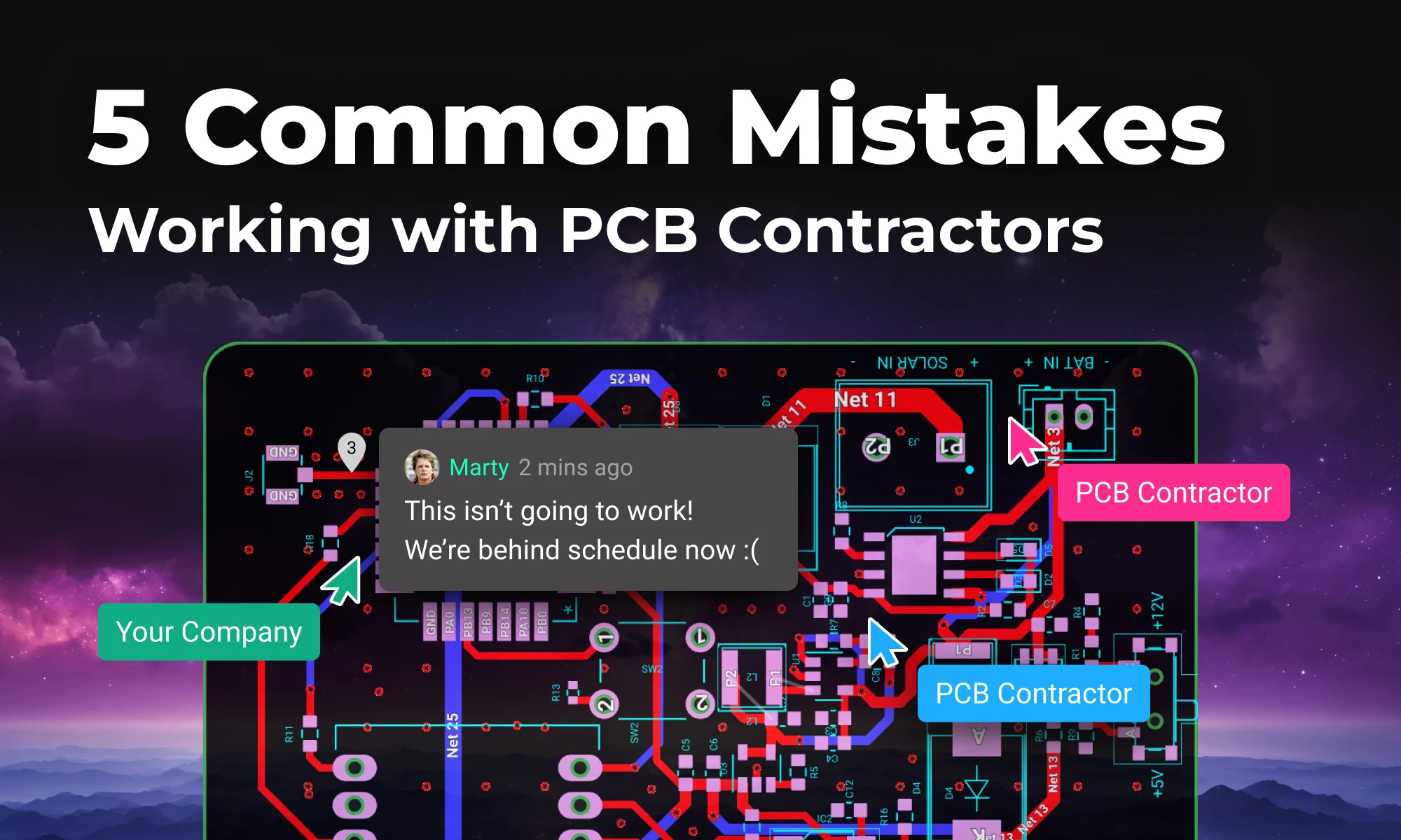
In this post, we’ll explore five common mistakes companies make when contracting PCB design and how you can avoid them by using tools like Flux to keep your project on track, from concept to completion.
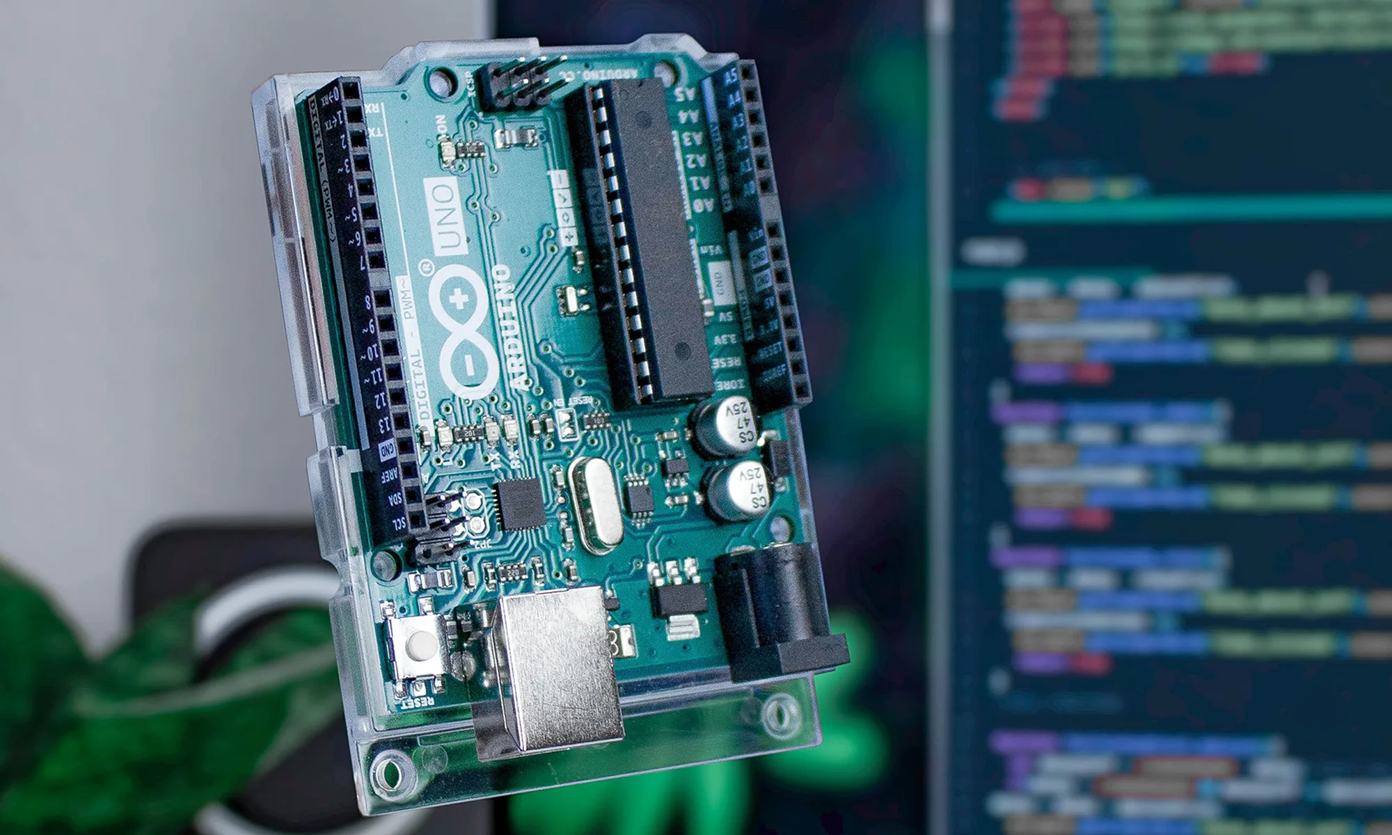
Explore the world of Arduino with a step-by-step guide on writing your first code and setting up a fundamental 'Blink' project to bring electronics to life.


A voltage drop calculator is an essential tool for assessing the decrease in voltage across a conductor, ensuring electrical devices receive adequate power for optimal operation. Read our blog to learn more.

Explore more than 20 new Flux Copilot prompts for hardware design. Accelerate brainstorming, component selection, validation and design review to streamline your PCB design.
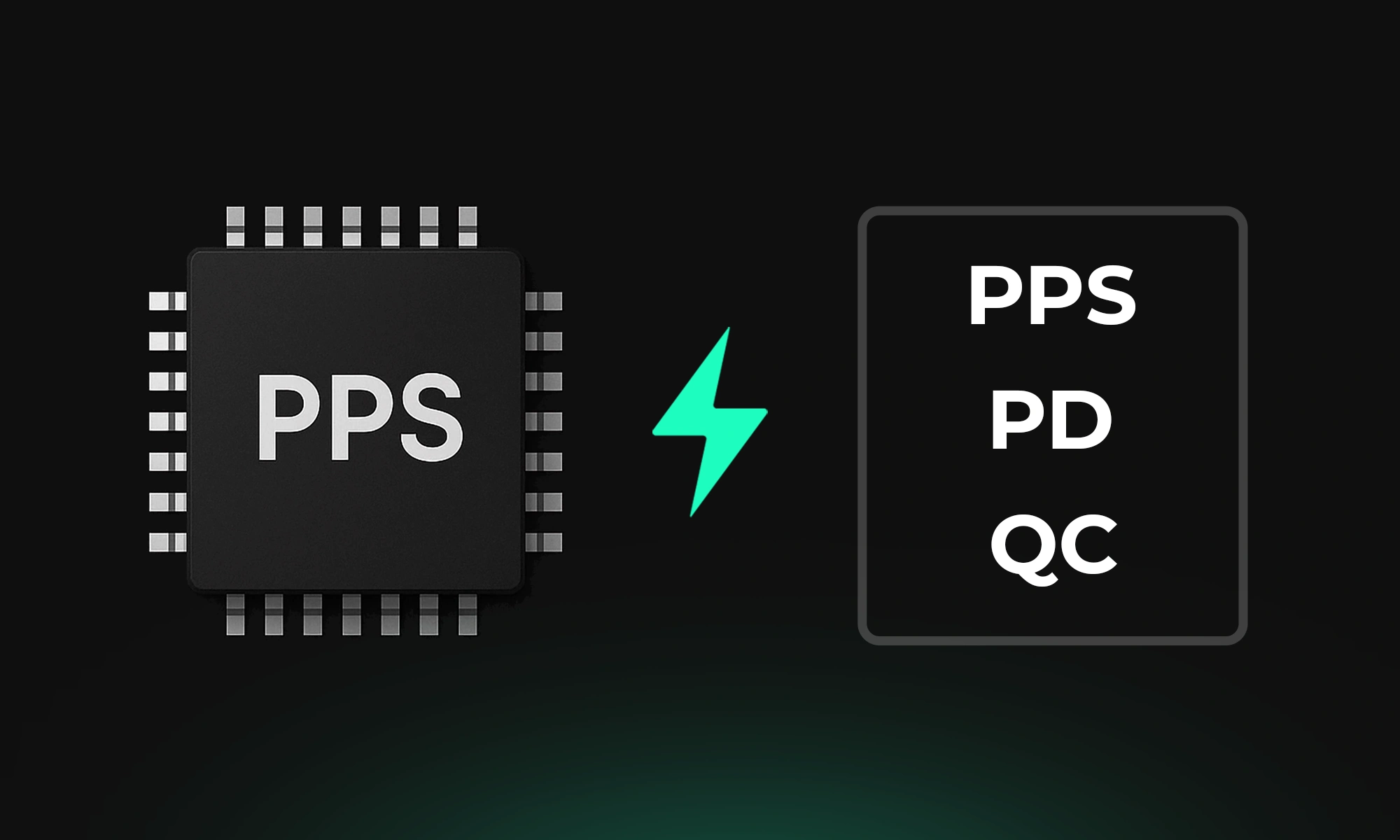
Fast charging has come a long way—and one of the most advanced technologies in this space is Programmable Power Supply (PPS). If you’ve ever wondered why your device charges faster with some cables and adapters than others, PPS might be the answer.

One of the key components of PCBs are vias, which are tiny pathways that allow electrical signals to travel from one layer of the board to another. Vias are a staple of PCB design.

Imagine designing a PCB in a third less time than you're used to - that's the power of Flux Copilot's new upgrade, allowing it to wire components together for you. In this tutorial, we'll walk you through the important workflows and example prompts to help you design a Raspberry-Pi-Pico-like board in 20 minutes.

Learn about STM32 microcontrollers, popular series, USB OTG, SWD, UART, and development tools. Find the right STM32 MCU and kickstart your projects.
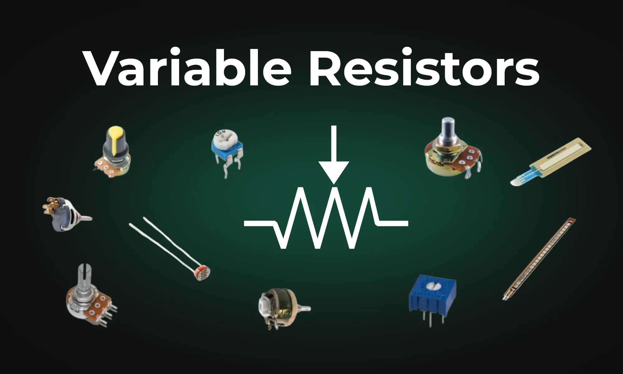
This article provides an overview of six types of variable resistors, including potentiometers, rheostats, photoresistors, wirewound resistors, thermistors, and varistors, highlighting their unique uses in electronic circuits. It also covers advanced applications and emerging technologies like digital potentiometers and memristors, emphasizing their significance in electronic control and adaptability.


This blog post explores the RS485 communication standard, renowned for its ability to facilitate long-distance, multidrop networking with enhanced noise immunity, making it a preferred choice for industrial settings. Dive into the post to understand RS485's key features and advantages over older protocols.

This blog post highlights a series of innovative reference designs developed by renowned manufacturers using Flux. These reference designs encompass a variety of applications, including advanced light sensing, robust data communication, and compact distance measurement. This diverse array showcases the adaptability and effectiveness of Flux in meeting the varied needs of industrial sensing applications